GPS Navigation System

Electrical

A simple GPS navigation system consisting of Arduino Uno, MPU9250 sensor used as magnetometer, OLED display.

Status

Finished

Timeline

2 weeks

Project Overview

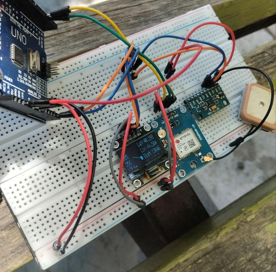
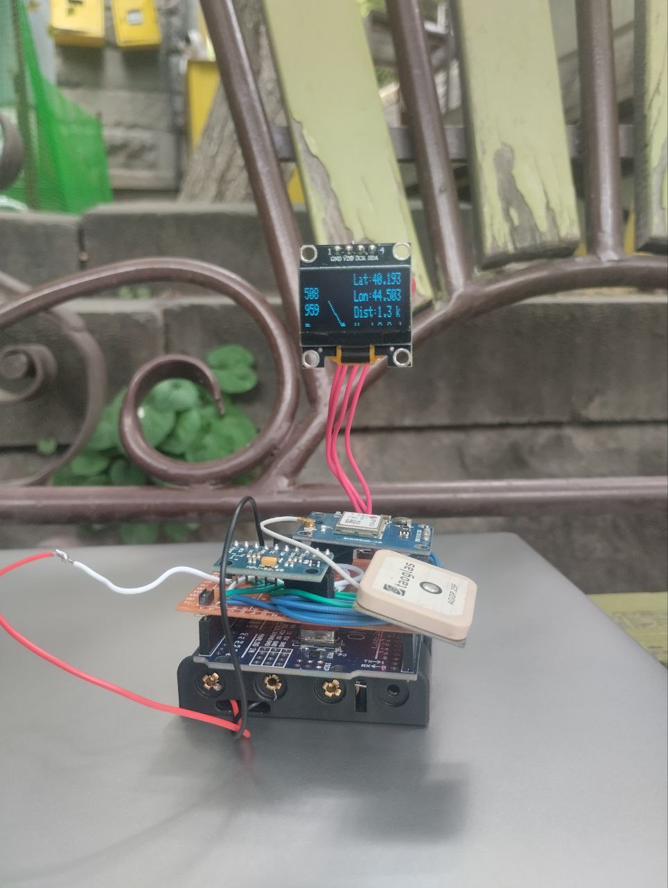
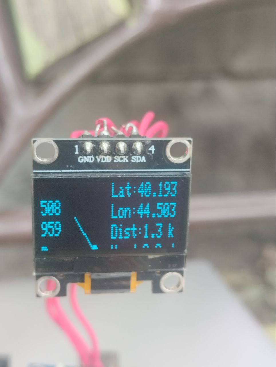
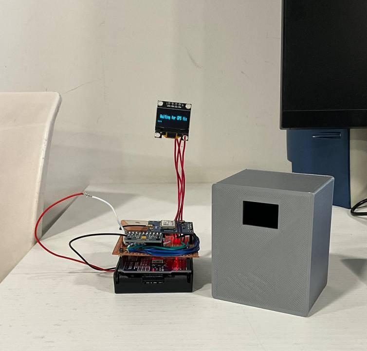
This project centers on building a GPS and compass navigation system using an Arduino Uno microcontroller, a GY-GPS6MV2 GPS receiver, a 128x64 OLED display, and an MPU9250 (specifically utilizing the magnetometer feature). The system is designed to retrieve real-time geolocation data and heading direction, then display this information visually on the OLED screen.

To understand the core principles of interfacing and working with the GPS module, the following guide was used:

How to Add GPS to an Arduino – Core Electronics

This resource provided foundational insights into GPS communication protocols (particularly NMEA sentences), parsing data using libraries, and general hardware integration considerations.

Technical Challenges

Software

Integrating multiple libraries (e.g., TinyGPS++, Wire, Adafruit_SSD1306, Adafruit_GFX, and libraries for MPU9250) introduced compatibility issues, particularly regarding I2C bus conflicts and memory limitations of the Arduino Uno.

Some GPS parsing libraries were too heavy or had conflicts with OLED display rendering when used together with the magnetometer drivers.

Magnetometer Calibration

The MPU9250’s magnetometer required careful calibration to eliminate hard and soft iron distortions.

Key Features

  • Real-time display of latitude, longitude, and derived location data on a 128x64 OLED screen.
  • Displays heading angle based on magnetometer data, pointing to magnetic North.
  • Compact and readable data layout designed for small resolution without clutter.
  • Optimized to run within the memory limits of the Arduino Uno.

Development Process

Phase 1: Hardware Integration

The GPS module was connected to pins 2 and 3 to not interfere with USB connection of the Uno. The MPU9250 and OLED shared the I2C bus, requiring careful address management. Power consumption and signal integrity were managed using decoupling capacitors and proper wire lengths.

Phase 2: Software Implementation

TinyGPS++ was used for parsing NMEA sentences efficiently. Minimal graphics libraries were used to control the OLED. Magnetometer values were read over I2C using a modified MPU9250 library. Code was developed iteratively, starting with individual module testing (GPS, OLED, then magnetometer), followed by integration and optimization.

Phase 3: Debugging and Tuning

Tested the system under a controlled wind source (fan). Refined blade angles and gear ratios for optimal performance.

Final Assembly and Results

The windmill was successfully able to rotate under moderate wind conditions (~2–3 m/s). The gear train amplified the blade rotation speed sufficiently to activate the motor. The motor produced a small but measurable voltage output, confirming successful energy conversion.